Dec 29, 2020 • Avik Das
I ended my last post about rendering curves in 3D with an example of a curve whose cross-sections end up mismatched at the ends. This is despite the fact that the curve uses the Rotation Minimizing Frame to define the cross-sections, meaning we don’t expect the curve to twist around. I went ahead and implemented a rendering of that curve to show what I mean:
(Link to screenshot if your browser isn’t new enough.)
If you consider a curve that’s planar, meaning it lies completely within a flat plane, that curve will never have this problem. Imagine walking on the “top” side of the cross-section. You’ll always be able to stay upright from start to end. Only when you move out of the plane would you end up pointing in a different direction along the way, and therefore in a different direction when you come back to your starting point.
What gives?
I don’t have a deep philosophical reason for why this mismatch sometimes happens on non-planar curves. But when it does happen, it means the Rotation Minimizing Frame wasn’t the best way to render that closed curve. Instead, we should have had the cross-section twist around so that by the time the curve closed in on itself, the starting and ending cross-sections line up.
We don’t want to apply this twist sharply at one point, so we can apply it incrementally across the entire length of the curve:
(Link to screenshot if your browser isn’t new enough.)
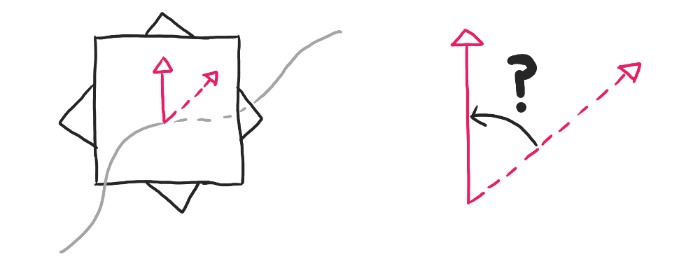
So how do we determine that $180^{\circ}$ is the right amount of mismatch to compensate for? Simply compute the Rotation Minimizing Frames at the start and end (which will require computing the frames in the middle), then compare the orientation of the two frames. Because the first and last frame should overlap, you can just compute the angle between the reference vectors $\hat{r}$ of the two frames.
Because the initial reference vector $\hat{r_0}$ and the final one $\hat{r_n}$ are on the same place, you can find the angle between them using the dot product between them (remembering that the vectors are unit vectors with length $1$):
\[\begin{align} \hat{r_0} \cdot \hat{r_n} &= \| \hat{r_0} \| \| \hat{r_n} \| \cos\theta \\ &= \cos\theta \\ \theta &= \arccos(\hat{r_0} \cdot \hat{r_n}) \end{align}\]Here, $\theta$ is the end-to-end twist we were looking for. We can just linearly interpolate this overall twist across the rendered frames, rotating each frame a fraction of the full twist until the entire twist is accounted for.
In the same way that the compensating twist for a mismatch can be interpolated along the curve, so can any additional twist. In particular, adding a multiple of $360^\circ$ on top of any compensating twist will still leave you with matching ends. You can see that with any of the curves in the visualization below:
(Link to animated screenshot if your browser isn’t new enough.)
What’s really interesting about these curves is that they are all “equivalent”, at least under certain transformations I’ll talk about more in the next post.
One thing you may have noticed from the twist calculation above is that the range of $\arccos$ is between $-180^\circ$ and $180^\circ$. That makes sense, in that two vectors can only be up to $180^\circ$ apart on the same plane. However, if you start with a small twist and transform the curve gradually, you may end up accumulating twist along the way.
The easiest way to see this is by “unfolding” a figure-8 loop, which you can see in the interactive demo below:
(Link to animated screenshot if your browser isn’t new enough.)
We start with a pretty normal figure-8, though one of the arms has been offset a bit to show how the unfolding will proceed. Over time, the curve flattens itself out into a circle, but notice what happened to the rotation of the frames along the circle. In order to preserve the relative orientation of the frames along the curve, the unfolding accumulated $360^\circ$ of twist!
A planar circle can be rendered without any end-to-end twist, just like any planar curve. But what the demo hints at is that a figure-8 with no twist and a planar circle with no twist are not equivalent! At least not equivalent under the unfolding transformation that we did. Instead, a figure-8 with no twist is equivalent to a planar circle with $360^\circ$ of twist.
This process of accumulating twist over the course of a transformation plays a big part in my research, something I’ll cover in more detail in the next post.
The idea of a curve twisting is central to my undergraduate research. Non-planar curves can end up with mismatched ends when rendered using Rotation Minimizing Frames, and when that happens, compensating twist has to be added to the curve. Curves can also have some amount of additional twist, which can be applied the same way as the compensating twist.
With the concept of twist established, the next post will talk about how a curve’s twist is somehow intrinsic to the curve, and only changes in very specific ways when the curve is transformed.